Sunday, September 30, 2018

IC 5146 - The Cocoon Nebula


The Cocoon Nebula is an emission and reflection nebula in Cygnus. It is 4000 light years away and spans 15 light years across (it has a visible size of 12 arc minutes - the full moon is 31 arc minutes).
(click image for full resolution image)

The brightest (red) parts of the nebula is the emission part - the darker parts with the blue hue are illuminated by the central star with the unassuming name "BD +46°3474". It's a very young star (~100,000 years!), it is 5 times larger than the sun, has 15 times the mass of the sun and shines 20,000(!!) times brighter!!! The nebula is very young - many stars are still "pre-sequence" stars (i.e. they are not shining visibly yet).

Processing this image was challenging because of the bright emission parts and the darker dust lanes around it. In my initial attempt, I focused too much on the bright, red part and its details and cut out almost all of the dust lanes:

I found it surprisingly difficult to process this image better. In order to do that, I tried out a couple of new things:

  1. Using the NBRGBCombination script in Pixinsight
  2. Carefully adjusting color levels using CurvesTransformation to bring out the red in the core and the blue in the faint regions
  3. Using a very fuzzy mask for processing the core that slowly increases protection over the faint, outer layers.

Using a (very) fuzzy mask to process nebula with faint outer areas

The image of the Cocoon nebula had a very bright core and a large area of fainter outer areas. When making adjustments (e.g. bringing out details in the core) I needed a mask that:
  1. Does not protect the bright core of the nebula
  2. Slowly faints out to the outer layers of the nebula
  3. Does protect the darker areas
I used the RangeSelection process for this.

The best way to do that was to first create a Preview over the nebula and the outer layers:

Then I open up RangeSelection and open the preview:


In order to get the transition between the core and the dark areas, I use a very high value for "Fuzziness" (I used 0.7). Now, when I move the "Lower Limit" slider to the right, I can see that the mask is very fuzzy:

The advantage of using a preview for this step is not only that I can zoom into the nebula, but also, that instead of creating a new image, the process overlays the resulting mask over the preview:

Now, I can toggle easily between image and mask (using the preview toggle button) to see exactly what parts of the nebula are strong protected and how it faints out. This first attempt was a little bit too large. I increase the "Lower Limit" a little and apply again:

Now, the brith parts are covered, but the mask isn't fuzzy enough (it doesn't cover the dark lanes enough). So, I increase Fuzinness - which decreases the cover of the inner parts. Upon which I decrease "Lower Limit" again to protect more. I play with these two settings until I have a combination that covers the bright parts and slowly degrades over the dust lanes:

Finally, I create the mask on the whole image and apply the mask:

Now, with this mask in place, I use LocalHistogramEquilization to bring out more details:

The process works very strong in the bright areas and then gradually fades towards the fainter regions!

Adjusting red and blue colors in an emission / reflection nebula

In my recent image of the Cocoon Nebula, I needed to adjust the red and blue colors very selectively:
  1. Keep the red in the core of the nebula (or maybe even increase it)
  2. Reduce the red in the fainter dust lanes
  3. Reduce the blue in the core of the nebula (to make it less pink and more red)
  4. Increase the blue in the fainter dust lanes
I use the CurvesTransformation process for this:

First, I want to increase the red in the inner parts and decrease the red in the outer parts. For that, I click in the inner parts, the dust lanes around it and the dark sky parts and notice where these points are in the diagram in the CurvesTransformation process:
Level in core part of the nebula
Level in dust lanes
Level in dark parts of the sky
Now, I set three points at these different levels:

This now allows me to adjust the levels in these three regions independently with smooth transitions in between:

I the same for the blue channel:

Only here, I decrease the level in the core (to make the core look less pink and more red), increase slightly in the fainter outer regions and decrease in the sky areas.

Now, the sky has a greenish hue (due to reducing the red in there). I also decrease the green in this area (but leave it in the other areas):

This now neutralizes the background without changing the color of the nebula or the faint dust areas.

Compare before and after:

Using the NBRGBCombination script in Pixinsight

In the past, I combined my narrowband data with LRGB images using a tutorial from LighVortexAstronomy. I tried the previous scripts in Pixinsight but they never really worked for me.

First, I use BackgroundNeutralization, ColorCalibration and SCNR on the RGB image to get the colors right. I also use DynamicBackgroundExtraction on the Ha and OIII images to clean up their background (I didn't do this on the RGB images as they are almost completely filled with stars and dust lanes).

This script has a fairly simple interface:

The first step is to select the RGB image and the narrowband images and press "Apply". The script opens a preview window where it shows the result of the combination:

One of the most useful feature are the two buttons RGB and NBRGB. They allow to flip from pure RGB to Narrowband+RGB picture and back. This makes it very easy to see the impact that the narrowband image(s) have.

See the difference between my RGB image and the combined image with default settings:

 
Pure RGB ImageCombined Image

The Ha data really brought out the red of the nebula. But unfortunately too much as the dust lanes are now also red. In order to reduce the impact, I increase the Scale setting for the Ha data. The default is 1.20, let's increase it to 3 (and click Apply again):

This is better, but the hue of the dark lanes are still very red. I tried various settings in the script, but could not increase the blue / decrease the red further without destroying the nebula). I decided to address this later with masks and CurvesTransformation.

One big caveat of this script:
IF YOU PRESS CANCEL WHILE IT'S RUNNING, PIXINSIGHT MIGHT COMPLETELY CRASH ON YOU (AND ALL UNSAVED PROGRESS IS LOST)!!! (Happened to me several times)

Saturday, September 15, 2018

M31 - The Great Andromeda Galaxy

This is the first of several images that I took at Lake San Antonio. Originally we wanted to go to Likely Place, but the wildfires destroyed the awesome dark skies up there :-( Lake San Antonio isn't super dark, but considering that it it just 2+ hours away from us it is pretty good.

(click on image for full resolution)

I n order to bring out the core, I used two different exposures: 600s/450sec and 60/45sec (for 1x1 and 2x2 binning). I used the tutorial from Light Vortex Astronomy - which was very good as always. In the end, it didn't make a huge difference. I probably should have rather taken only long exposures to get the faint details in the outer regions. In addition, I took Ha images after we returned home to bring out the nebulae.

I had to fiddle with the sequence of processing:

  1. Calibrate, align and stack the individual exposures (I ended up with 2 sets of LRGB images and one Ha image)
  2. Remove Gradients with DynamicBackgroundExtraction
  3. Combine the two different exposures with HRDComposition
  4. Combine the RGB images with LRGBCombination
  5. BackgroundNeutralization and ColorCalibration of the RGB images
  6. Folding in the Ha data
  7. BackgroundNeutralization again (the background was on the red side after folding in the Ha data)
  8. then processing as normal
Processing was surprisingly difficult. I assumed that processing images from the RH200 scope under dark skies would be easy. But the background gradients were surprisingly strong.

As many astrophotographers, M31 was one of the first images I ever took:

Amazing what difference 6 years of experience (and a lot of $$$ for better equipment) make :-)

Sunday, September 2, 2018

Imprecise slews after successful model building

At our recent trip to Lake San Antonio and afterwards I had a strange problem:

I polar align my RH200 scope. I build a model - RMS < 5.0.

But the slews are very imprecise.

SGPro can still center the object.

Afterwards, tracking is very precise.

...

I spent a lot of time trying to figure out what's happening. Some observations:

  • the slews are always the same, i.e. a star always ends up in the exact same place on my image (somewhere in the lower right corner)
  • building the model with more or less points has no impact
  • tried various parameters in the 10Micron handset (with / without refraction correction, set refraction parameters by hand, switch from J2000 to JNow in the ASCOM driver...) - always the same
I posted in the 10Micron forum, but nobody had a good idea.

Then, in the last nights I first thought that I figured something out. After model building I could slew with the handset to a start and it would be precisely in the center! But then I realized that TSX had still subframes on. When I turned them off, the slew were as before.

...

THAT was the clue! Normally, the slews should be precise with or without subframe as the subframe should be in the center of the image!!!

More analysis. Yes, ModelCreator creates a subframe in the lower right corner of the image (it uses width/2 for width AND left side and height/2 for height AND upper side!!!)

Once I used no subframes, everything worked again. Yei! Martin (he creator of ModelCreator) told me that he'll fix this in the next release of ModelCreator.

... but it cost me several hours of imaging time at Lake San Antonio when the Meridian Flip failed due to this issue ... :-(

Wednesday, July 11, 2018

North America Nebula and Pelican Nebula

The North America Nebula (left) and Pelican Nebula (right) are one(!) large emission nebulae in the constellation Cygnus.

(click on image for full resolution image)

This image consists of almost 25 hours of data (3 hours Ha, 9 hours SII and almost 13 hours of OIII).

The nebula appears four times the size of the full moon. It's real size is 50 light years in diameter - it's at a distance of 1800 light years from earth. It was "probably" discovered by William Herschel on October 24, 1786 - or by his son before 1933 (William Herschels notes weren't clear if he meant this particular nebula).

The big, black divider in the nebula is actually a dark dust cloud between the nebula and earth - the nebula itself is continuous. It visually splits the nebula in the two nebulae.


The nebula gets excited by the blue, super hot star HD 199579.


As many emission nebulae, the North America Nebula also has several regions of star formation. The most concentrated area is the so called Cygnus Wall:

This is the first image with my new Officina Stellare RH200 telescope on the 10Micron HPS 1000 mount. It took me a loooooong time to collimate and align the RH200 telescope and also quite a while to setup the 10Micron mount. But now I can image completely unguided (it's awesome that all the modelling algorithm and such is on the mount and not yet another piece of software on the computer - makes things much more simple and stable).

I also tried a few new processing steps:
  • I did Noise Reduction and stretching on the separate images before combining. This lead to an image that was much more balanced from the beginning.
  • I used AutoHistogram for stretching. Really liked it as it allowed very fine control of background and overall level.
  • I used the DarkStructureEnhance script to bring out more details in the dark dust lanes.

Tuesday, July 10, 2018

Using the DarkStructureEnhance Script in Pixinsight

For my image of the North America Nebula, I used Pixinsights DarkStructureEnhance script for the first time:


It's a rather simple script. Select the image that you want to tackle. The only parameter I need to play with is the Amount. Setting it to higher values to enhance more and lower to have less of an effect. The default of 0.4 worked well.

Before:After:
It's a subtle, but noticeable difference.

I like processes like these: not too many parameters, easy to control and achieve small improvements.

Sunday, May 27, 2018

Collimating and aligning the RH200

So, I finally collimated and aligned my RH200 scope good enough (still not perfect, but good enough to start imaging).

This post should really have been a series of posts to describe all the avenues I went - but I compress it into one ...

Let me start with what steps finally worked:

  1. Good (not perfect) collimation with Mire de Collimation
  2. Perfect collimation and very good alignment with Hotech Laser Collimator
  3. Final alignment with CCDInspector
1. Good (not perfect) collimation with Mire de Collimation
I was very much surprised how a simple tool like this can be so helpful. I used it together with TheSkyX and overlayed it on the image view. I used the continuous imaging and tried to size the rings in Mire de Collimation such that one ring was just inside the out-of-focus donut:


First, I worked on the primary mirror collimation. I experimented to understand which collimation screw has which effect. This helped A LOT when I then tried to get the out-of-focus donut concentric.

One problem was that I couldn't reach the collimation screws because the Atlas focuser was in the way:

The solution was to turn the Atlas focuser around, so that it extends from the scope when I move it out of focus.
I had the best luck with bright (not THE brightest) stars. This gave a good donut but allowed me to use short exposure times (1 seconds) which made it easier to see the effect of collimation adjustments.
My workflow was:
  1. center out-of-focus star
  2. overlay Mire de Collimation perfectly concentric
  3. adjust one(!) collimation screw
  4. re-center out-of-focus-star
  5. <go back to #2>
Once I figured out the workflow it took just a few nights to get the collimation of the primary mirror.

Once the collimation looked good, I moved onto the front plate. My front plate was initially WAY too tight. The in-of-focus start showed really bad aberrations. I loosened it and used the same process as above to adjust the plate. Because of limited focus range, I couldn't get the star as good in-of-focus as I could get it out, but it was good enough:

After I changed the plate, I also had to redo the primary mirror collimation. It took me a few iterations to get both good.
  • using CCDInspector to collimate main mirror and/or front lens - didn't work well
  • using CCDInspector to collimate front lens (ask on forum!!!)
  • tried collimation mask - didn't work (plus: front or back?)
  • posted in OS forum
  • Miere de Collimation - yes, simple and works!!!
2. Perfect collimation and very good alignment with Hotech Laser Collimator

This step took me the longest to figure out (see below all methods that I tried and that didn't work). I could get the collimation good - but not perfect. I ended up forking off the $$$ to buy the Hotech Laser Collimator - and it was SOOO worth the money!

First, I put the laser collimator head on my very sturdy DSLR tripod:

Then I stepped through the process to collimate and align the scope:
  1. Align the scope with the collimator
  2. Collimate the primary mirror
  3. Align the imaging train
The key in getting great results was #1. I ended up spending 2 nights just doing this. I needed to put on my reading glasses to see very exactly if the three laser dots were in the same position all around:

Again, not difficult to understand but needed a lot of patience and many iterations to get really good.

Then I moved on to collimate the primary mirror. Because it was already well aligned, this didn't take too long, but I could improve it.

The alignment caused me most headache. After I did it the first time, I rotated the special mirror piece around:
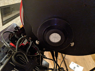
And then the imaging train wasn't aligned... ... I figured out that this was because the mirror at the end of train is not necessarily completely orthogonal to the optical axis. What I ended up doing was to rotate the eyepiece around and mark the inner- and outermost position of the 3 laser points. The middle point was where I needed to get the laser point to.

Excluding setting up and learning about the laser collimator, this took me 3 nights.

3. Final alignment with CCDInspector
Now, I moved the scope outside and did the final alignment using CCDInspector. I used the flatness view to see which corner/side was too far in the front / back (I always had to experiment if I needed to move this corner in or out to correct).
At this point, I made tiny corrections (1/8 of a turn of the alignment screws) - always checking if and how much the plane changed.
Once the plane looked fairly plane, I used the average of first 5 and then 10 images for final adjustments to make sure that didn't end up chasing seeing.

One weird thing happened was that after I had the alignment almost perfect, I moved the scope to the other side of the pier and got this:

On closer analysis, I realized that one of the lock screws wasn't completely fastened. That fixed it. But it also showed how incredible sensitive the scope is to even slight errors.

So, yei! I finally had it. Took me only 3(!!) months ...

Things that I tried that didn't work:

  1. Using CCDInspector for collimation
    I really don't know how this works (I tried both the in-focus and out-of-focus method). I could see with my naked eye that the donut wasn't concentric... Also, for rough collimation the adjustments were so large that I had to refocus A LOT - which made the process really slow.
  2. 4 corner view in TSX
    The visualization was good:
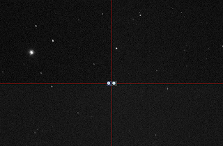
    But I found it too difficult understanding from the picture what adjustments I had to make
  3. Collimation mask
    This only worked for rough adjustment and I found it easier and faster to use Mire de Collimation.

Sunday, May 13, 2018

Heart Nebula (IC 1805)

I took the data for this image October 2016 (!!!) It's a mosaic of 4 images and I always had problems stitching them together. Especially the OIII data which had very different noise levels in the 4 panels. But I finally figured out a way to minimize the effect! As always an awesome tutorial from Light Vortex Astronomy helped me!

(click here for a full-resolution view)

The Heart Nebula is at a distance of 7,500 light years from earth in the Perseus arm of our galaxy. It spans 200 lightyears! The nebula is ionized by the relatively young stars at the center of the nebula (their open star cluster is known as Melotte 15). The nebula is 150 arcminutes in size (the moon is 30 arcminutes!) in the constellation Casiopeia.
It was discovered by William Herschel on November 3rd 1787 (he first discovered the brightest part in the lower left - NGC 896).

Being a mosaic there is SO much interesting detail here:

1. The bright NGC 896

2. The open star cluster Melotte 15 at the core


3. Beautiful dust pillars (created by the energetic light from the young, hot stars at the center)

Each of the four panels has and integration time of 10 hours (10xHa, 20xOIII, 40xSII - each 10 minutes). I think this is the longest integration time I ever had.

Saturday, May 12, 2018

Mosaic with different background levels

Taking the images for my mosaic of the Heart Nebula took a long time (several weeks). And as a result the background levels of the different panels were quite different (mostly because of the moon). This was most noticeable in the OIII channel:

Here is mosaic of them without modification:

The first advice that I found was to remove backgrounds as much as possible using ABE or DBE. That made it better, but the differences were still very noticeable.

On one thread in the Pixinsight forum, somebody recommended to use LinearFit to equalize the levels - but that did not work at all for me:

The histogram got completely squished...

On another thread, somebody mentioned AutoHistogram:

The usage is fairly straight forward: select the image that you want to use as a reference image (preferably the image with the largest range) and click on "Set As Active Image". This reads out the median pixel value of the selected image to be used for the adjustment.

Then you just apply this process to all the other images:

Doing this to all images and combining them with GradientMergeMosaic results in:
Yei! That looks much better! I had to play with the Feather Radius to avoid a pinched star, but apart from that it was now straight forward.